10.3 UART transmitter
The UART transmitter block diagram is shown in Fig. 10-2. The heart of the transmitter is the transmit shift register UxTSR where parallel data (9-bit word) are converted to serial data sequences. The shift register obtains its data from the transmit FIFO buffer, TxTXREG. The write-only UxTXREG register is loaded with data by the user software. The UxTXREG is not loaded until the STOP bit has been transmitted from the previous load. As soos as the STOP bit is transmitted, the UxTSR is loaded with new data from the UxTXREG register (if available).

Fig. 10-2 UART transmitter functional block diagram
Attention!
The registers UxTXREG and UxTSR are 9-bit wide, i.e. data write to the transmit FIFO buffer through the register UxTXREG is done in bytes (8-bit). The UxTSR register is not mapped in data memory, thus it is not available to the user.
The UART transmission is enabled by setting the UTXEN enable bit (UxSTA<10>). The actual transmission will not occur until the UxTXREG has been loaded with data and the baud rate generator has produced a shift clock, in accordance with the value in the register UxBRG. The transmission can also be started by first loading the UxTXREG register and the setting the UTXEN enable bit.
Clearing the UTXEN bit during a transmission will cause the transmission to be aborted and will reset the transmitter. As a result, the UxTX pin will revert to a high-impedance state.
In order to select 9-bit transmission, the PDSEL<1:0> bits (UxMODE<2:1>) should be set to '11' and the ninth bit should be written to the 9th location of the UxTxREG register (UxTXREG<8>). A word (16-bit) should be written to UxTXREG so that all nine bits are written at the same time.
\
NOTE: There is no parity in the case of 9-bit data transmission.
The data transmit FIFO buffer consists of four 9-bit wide memory locations. The UxTXREG register provides user access to the next available buffer location. The user may write up to 4 words in the buffer. Once the first location in the transmit FIFO buffer is loaded to the shift register UxTSR, that location becomes available for new data to be written and the next location is sourced to the UxTSR register. The UTXBF status bit is set whenever the buffer is full (all four locations). If a user attempts to write to a full buffer, the new data will not be accepted into the FIFO.
Attention!
The FIFO is reset during any device RESET, but is not affected when the device enters SLEEP or IDLE mode or wakes up from SLEEP or IDLE mode.
10.3.1 Transmit interrupt
The transmit interrupt flag (UxTXIF) is located in the corresponding interrupt flag status (IFS) register. The UTIXSEL control bit (UxSTA<15>) determines when the UART will generate a transmit interrupt.
- If UTXISEL = 0, an interrupt is generated when a word (8- or 9-bit) is transferred from the transmit FIFO buffer to the transmit shift register (UxTSR). This implies that the transmit buffer has at least one empty word. An iterrupt is generated very often. If the UART module is to operate in this mode, it is required that the corresponding interrupt service routine is very quick, i.e. it should be completed before the transmission of the next word.
- If UTXISEL = 1, an interrupt is generated when a word is transferred from the transmit FIFO buffer to the transmit shift register (UxTSR) and the transmit buffer is empty. Since an interrupt is generated only after all 4 words have been transmitted, this 'block transmit' mode is useful if the interrupt service routine cannot be performed very quickly.
Attention!
When the UTXEN enable bit is set, an interrupt request will be generated. The interrupt request should be reset by the user software. If UTXISEL = 0, an interrupt request will be generated on setting the UTXEN since there is at least one empty location in the transmit FIFO buffer; if UTXISEL = 1, an interrupt request will be generated on setting the UTXEN since the transmit FIFO buffer is empty.
While the UxTXIF flag bit indicates the status of the UxTXREG register, the TRMT (UxSTA<8>) status bit shows the status of the UxTSR register. The TRMT status bit is a read only bit, which is set when the UxTSR register is empty. No interrupt logic is tied to this bit, so the user has to poll this bit in order to determine if the UxTSR register is empty.
10.3.2 Setup for UART transmit
When setting up a transmission, the following steps should be undertaken:
- Initialize the UxBRG register for the appropriate baud rate.
- Set the number of data bits, number of STOP bits, and parity selection by writing to the PDSEL<1:0> (UxMODE<2:1>) and STSEL (UxMODE<0>) bits.
- If transmit interrupts are desired, set the UxTXIE control bit in the corresponding interrupt enable control register (IEC). Specify the interrupt priority usin the UxTXIP<2:0> control bits in the corresponding interrupt priority control register (IPC). Select the transmit interrupt mode by writing the UTXISEL (UxMODE<15>) bit.
- Enable the UART module by setting the UARTEN (UxMODE<15>) bit.
- Enable the transmission by setting the UTXEN (UxSTA<10>) bit. This will also set the transmit interrupt flag UxTXIF bit. During the initialization, the interrupt request of the UART module transmitter UxTXIF bit should be cleared. Also in the interrupt service routine the interrupt request UxTXIF should be cleared.
- Finally, load data to the transmit FIFO buffer by writing to the UxTXREG register. If 8-bit transmission is used, load a byte (8-bits). If 9-bit transmission has been selected, load a word (9-bits, higher bits are ignored).
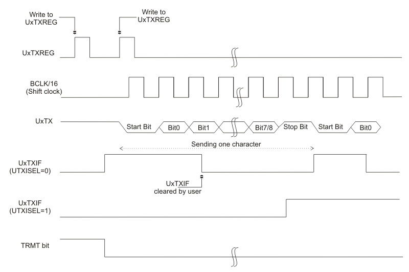
Fig. 10-3 shows the waveforms of an example of serial data transmission (8-bit or 9-bit) by the UART module. Fig. 10-4 shows the waveforms of an example of serial data transmission for a sequence of two bytes.

Fig. 10-3 Waveforms of serial data transmission (8 or 9-bits)
Fig. 10-4 Waveforms of serial data transmission (sequence of two bytes)
For sending a break character (symbol), the UTXBRK (UxSTA<11>) bit must be set by software. Setting this bit forces the output pin UxTX to logic zero. Setting the UTXBRK bit will override any other transmitter activity. The user should wait for the transmitter to complete the current transmission before setting UTXBRK.
To send a break character, the UTXBRK bit must be set by software and remain set for a minimum of 13 baud clocks.The baud clock periods are timed in software. The UTXBRK bit is then cleard by software to generate the STOP bit (one or two, defined by the configuration). The user must wait one or two baud clocks to ensure a valid STOP bit(s) before loading data to the FIFO buffer via the UxTXREG register.
Attention!
Sending a break character does not generate a transmitter interrupt.